
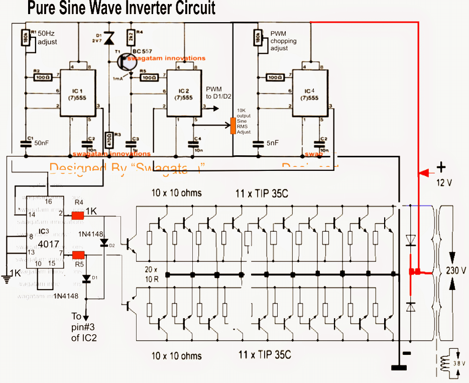
Make This 1KVA (1000 watts) Pure Sine Wave Inverter Circuit Circuit Diagram Centre
output generated: modified sine wave, and pure sine wave1. A modified sine wave can be seen as more of a square wave than a sine wave; it passes the high DC voltage for specified amounts of time so that the average power and rms voltage are the same as if it were a sine wave.
1KVA (1000 watts) Pure Sine Wave Inverter Circuit using 555 ic Expert Circuits
But the difference between modified and pure sine wave inverters is that these types of inverters are not suitable for inductive loads such as motors, fans, etc. that's where pure sine wave inverters come into play. They output a pure sinewave at line frequency so that it won't affect such inductive loads.

12v To 220v Pure Sine Wave Inverter Circuit Diagram
The Bootstrap supply technique is a simple, cost-effective way to power the upper MOSFET's gate and provide bias supply to the floating logic sections of the Gate Driver. Only two components (a Bootstrap diode and capacitance) per bridge phase are needed to implement the Bootstrap supply. Figure 4.

Pure Sine Inverter Circuit Diagram
Step 1: Highlights 1. Full bridge configuration based on power MOSFETs 2. DSP based intelligent control 3. LCD based display for user-friendly display of parameters and status 4. Protection against 440V mains input 5. Protection against reverse polarity 6. Dynamic short circuit protection with fold-back current limiting. 7.
7 Modified Sine Wave Inverter Circuits Explored 100W to 3kVA Homemade Circuit Projects
The 3000 Watt Pure Sine Wave Inverter Circuit Diagram provides clear guidance on the installation and safety measures required to ensure a safe operation. From the wiring connections to the components, the diagram ensures all elements are properly set up and connected so that your system operates efficiently and safely.
How to Modify a Square Wave Inverter into a Sine Wave Inverter Concept Explored Circuit
At this time, output of the power main circuit is a specific harmonic combination, which will obtain the waveform through the filter circuit. The basic structure of sine wave inverter is shown on the following diagram. Working Principle of Sine Wave Inverter. The function of a sine wave inverter is to convert direct current into alternating.
7 Modified Sine Wave Inverter Circuits Explored 100W to 3kVA Homemade Circuit Projects
Car batteries for powering you home? Build a low cost 12V to 220V (DC-AC) Pure Sine Wave Inverter from scratch! The project is based on the low cost EGS002 SPWM driver board module. The DIY inverter board can handle up to 1kW (depending the transformer size). Around $30 was spent to build this project from locally sourced parts.
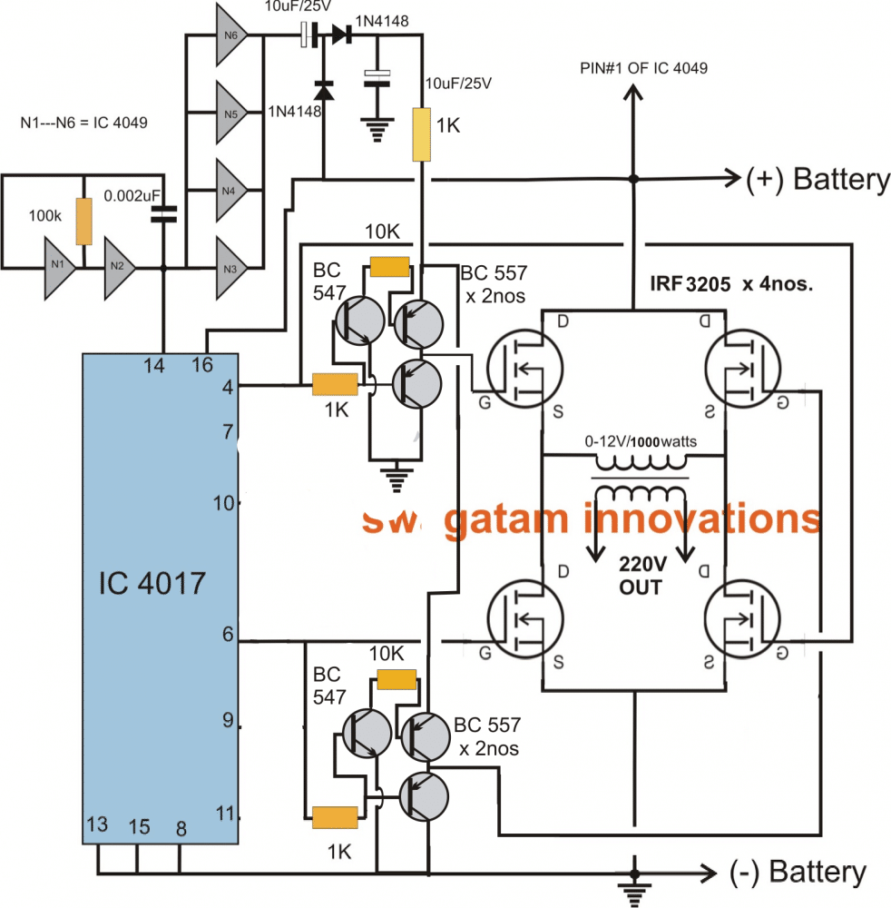
Make This 1KVA (1000 watts) Pure Sine Wave Inverter Homemade Circuit Projects
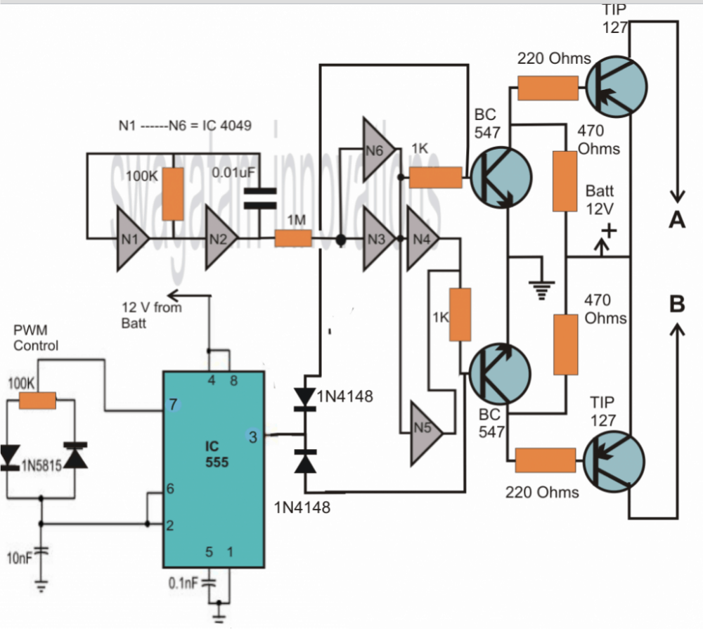
The updated diagram (recommended) can be witnessed below: The above design is the recommended one! (Just make sure to add the delay timer, as explained below!!) For the full Program Code please visit the following link: Arduino SPWM Generator Circuit Video Clip Parts List All resistors are 1/4 watt, 5% CFR 10K = 4 1K = 2 BC547 = 4nos

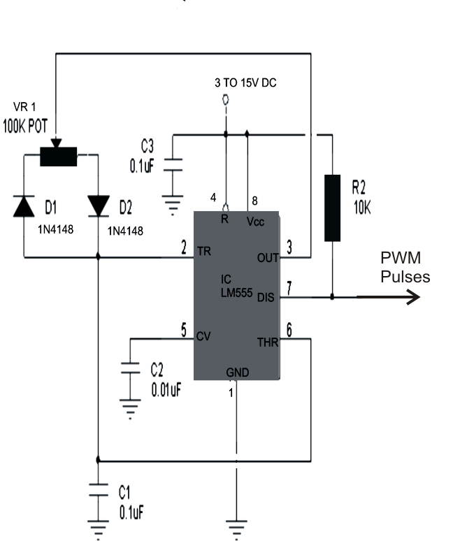
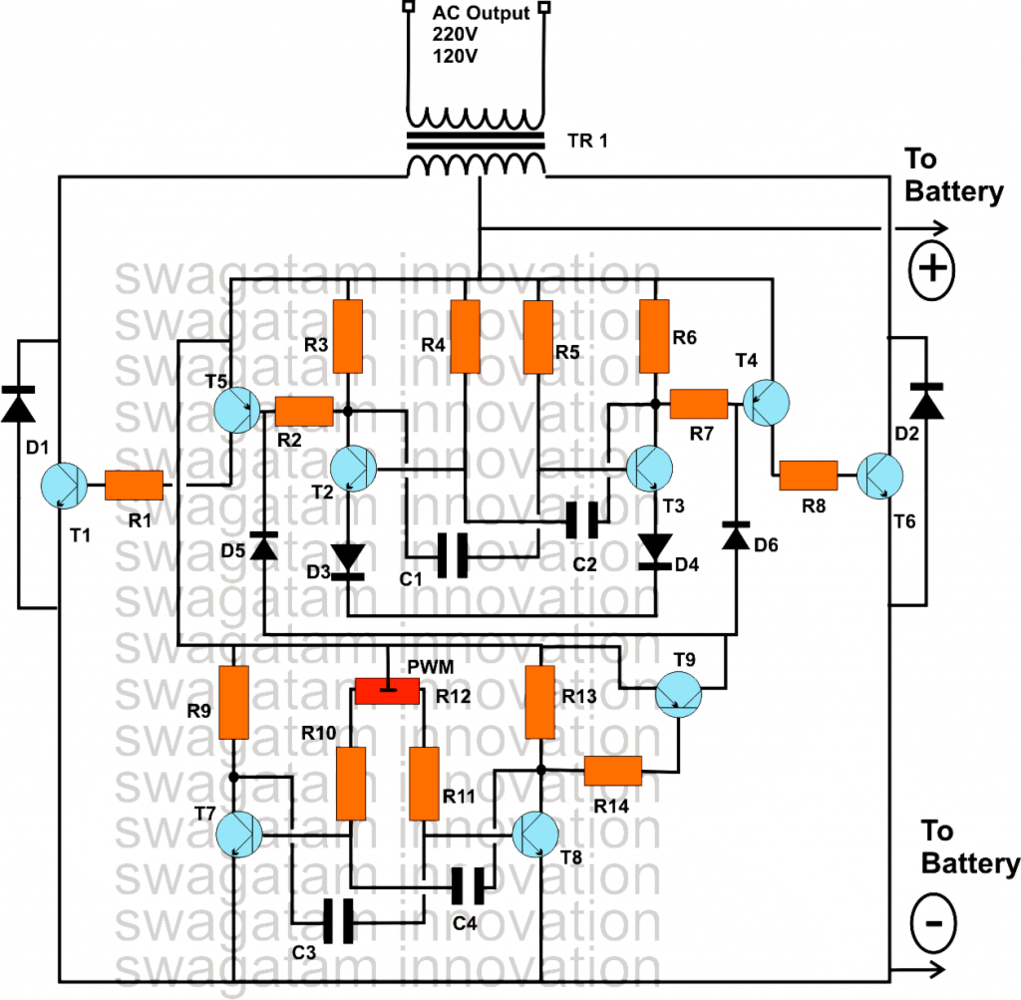
300 Watts PWM Controlled, Pure Sine Wave Inverter Circuit with Output Voltage Correction
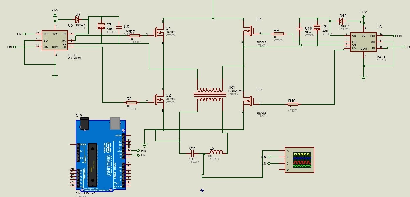
2.1.1 Inverter Mode: The method, in which the low voltage DC power is inverted, is completed in two steps. The first step is the conversion of the low voltage DC power to a high voltage DC source, and the second step is the conversion of the high DC source to an AC waveform using pulse width modulation.
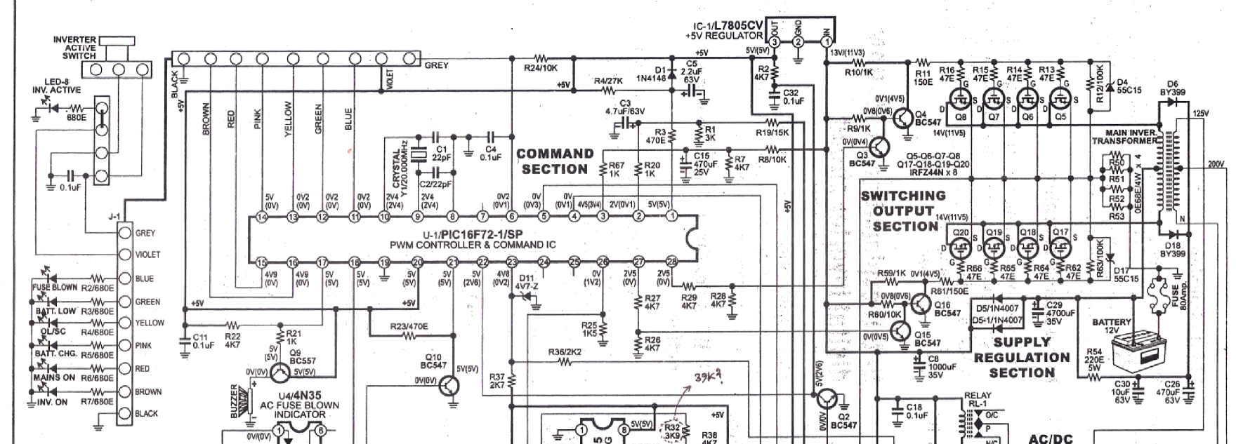
Sine Wave Inverter Circuit using PIC16F72
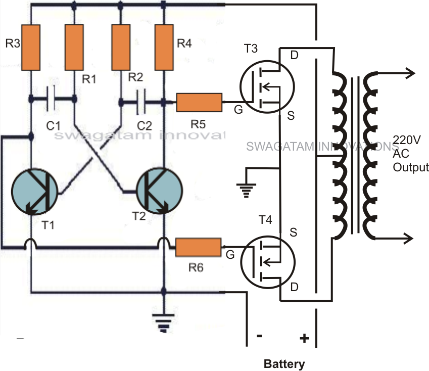
One is a more common inverter circuit diagram. The above is a relatively easy to produce the inverter circuit diagram, you can 12V DC power supply voltage inverter 220V mains voltage, the circuit from BG2 and BG3 composed of multi-harmonic oscillator to promote, and then BG1 and BG2 drive to control the BG6 And BG7 work.
Make This 1KVA (1000 watts) Pure Sine Wave Inverter Circuit Circuit Diagram Centre
A sine wave inverter is a device which converts battery power into a 220 V AC or a 120 V AC sine wave output. There are 3 basic types of inverters: square wave inverter, modified sine wave inverter and a pure sine wave inverter. The voltage waveform output from a square wave inverter is square wave.

300 Watts PWM Controlled, Pure Sine Wave Inverter Circuit with Output Voltage Correction
This article is all about the inverter circuit diagram. The inverter is an electrical device that is used to convert direct current to alternating current.. Modified Sine Wave Inverter These are the inverts that are cheaper than the inverter, as mentioned above. They are used in low electrical devices like fans, bulbs, microwave ovens, etc.
7 Modified Sine Wave Inverter Circuits Explored 100W to 3kVA Homemade Circuit Projects
So the circuit diagram for our Pure sine wave inverter using PIC16F76: Sine wave inverter circuit diagram. Here you can see that all the MOSFETs are driven with the help of TLP250 gate driver IC and associated circuitry. The control MCU is PIC16F76 which is generating 4 sets of signals and these signals are triggering the MOSFETs with the help.
single phase pure sine wave inverter using arduino
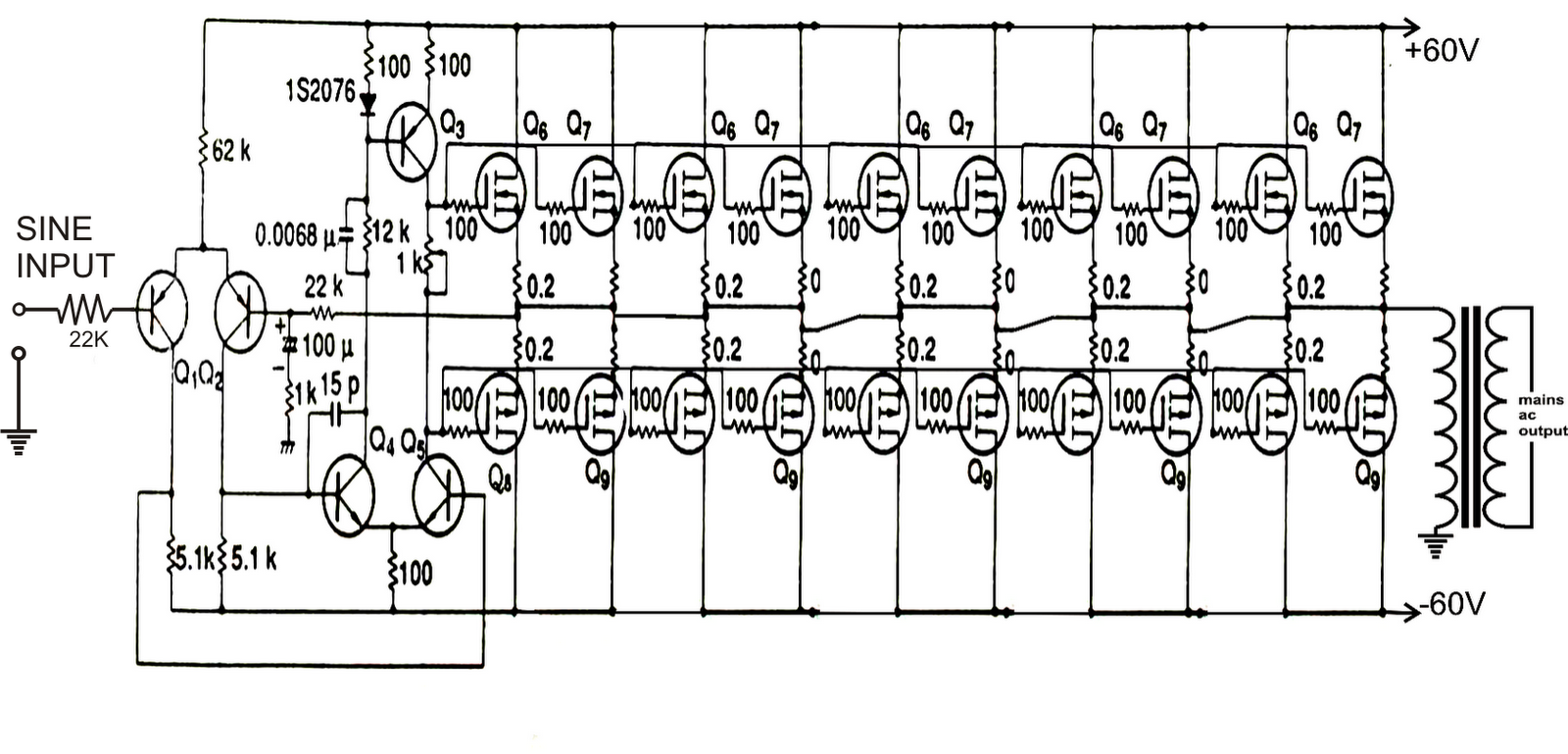
A relatively simple 1000 watt pure sine wave inverter circuit is explained here using a signal amplifier and a power transformer. As can be seen in the first diagram below, the configuration is a simple mosfet based designed for amplifying current at +/-60 volts such that the connected transformer corresponds to generate the required 1kva output.

Sine Wave Inverter Circuit Diagram Pdf
Parts List Sine Wave Inverter Circuit Diagram The DIY sine wave inverter circuit using IC 4047 is given below. - Advertisement - Sine Wave Inverter Schematic It comprises a CD4047 multivibrator (IC1), MOSFET, IRF250 MOSFETs (T1 through T8), transistors, and a few discrete components.
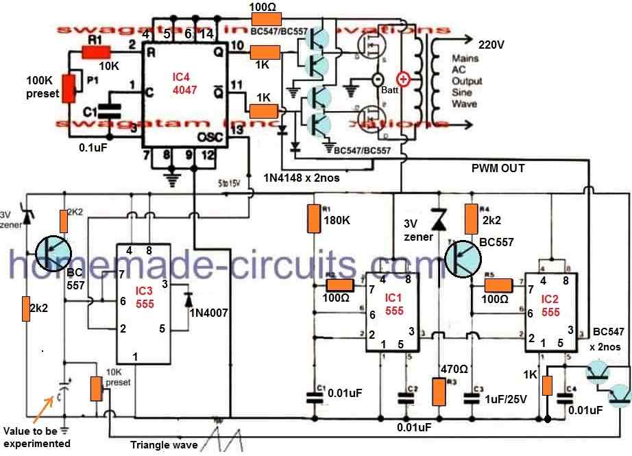
Pure Sine Wave Inverter Circuit Using IC 4047 Homemade Circuit Projects
Sine wave inverter circuit diagram with a complete step-by-step program and coding. In this article, we will discuss how to use a push-pull converter, sinusoidal pulse width modulation, an H-bridge, and a low-pass LC filter to create a pure sine wave inverter circuit diagram. I have already discussed all of these topics in the following articles.
